residual current operated circuit-breakers with integral overcurrent protection DRCBO 3 D13/0,30/1N-F
- sensitive to mixed frequencies, mains-voltage-independent
- higher system availability: short-time delayed
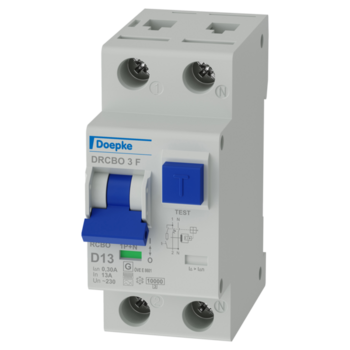

residual current operated circuit-breakers with integral overcurrent protection DRCBO 3 D13/0,30/1N-F
- sensitive to mixed frequencies, mains-voltage-independent
- higher system availability: short-time delayed
Details
Residual current operated circuit-breaker with integral overcurrent protection, one-pole+N, 13 A, 0,3 A, D-characteristic, Type F, short-time delayed
RCBOs combine residual current and miniature circuit-breakers in a single device (RCBO). They protect people against residual currents and systems against short-circuit and overload. Switches from series DRCBO 3 are independent of the mains voltage and have a high rated switching capacity. Separate displays enable a quick overview of the current operating conditions. DRCBO 3 can be conveniently installed and removed. Type F switches are mixed frequency sensitive. They protect against pulsating and AC residual currents as well as residual currents with mixed frequencies that differ from 50 Hz independent of the mains voltage. Switches with the D characteristic are optimised for electric circuits with strongly inductive consumers, such as lamp groups or power transformers. Their short-circuit trip value is above the value for classic line protection. Standard switches are designed for electric circuits with a rated voltage of 230 V or 400 V and a rated frequency of 50 Hz.
sensitive to AC residual currents and pulsating DC residual currents at the mains frequency (type A) as well as AC residual currents with multiple frequency components not equal to 50 Hz, compact design for all rated currents, high short-circuit resistance, green/red switching position indicator, residual current tripping indicator, Strain-relief clamps with protection against wires being lodged behind them and wide terminal cross-section range for rail and line wiring on both connection sides, Use of conventional wiring rails possible, Neutral conductor right, tri-stable snap-in slider for easy mounting and removal, high electromagnetic compatibility (immunity to interference for industrial applications)
quick fastening to mounting rail, any installation position, supply as desired
Protection of circuits in residential and purpose-built buildings as well as industrial facilities with TN-S, TT and TN-C-S networks. In IT networks, the RCCB/MCBs can be set to switch off in the event of a second earth fault, perfect for single-phase frequency converters, installations with switching power supplies and LED lighting, Not permitted for use in systems with TN-C networks; not permitted for protecting circuits in which the power electronics equipment may cause smooth DC residual currents or residual currents with frequencies not equal to 50/60 Hz.
- Operating instructions
- Data sheet
- Technical information derating graph
- Technical information dissipation power
- Prospectus DRCBO 3
- Prospectus Circuit-breaker overview
- Text for invitation to tender RTF
- Text for invitation to tender GAEB XML
- Text for invitation to tender GAEB 2000
- Text for invitation to tender GAEB 90
- Dimensional drawing Group view
- STEP file
- Wiring diagram

