
To protect people against electric shock, which in the worst case, if not properly done can cause serious injuries leading to fatal consequences. So, the right electrical protection is essential. In the event of an electrical accident, the question always arises as to who has technically tested the charging station after the final installation and approved it. So, who could be held responsible for the accident? Technical testing in accordance with the specifications is therefore indispensable.
Current practice: residual current protection EV Charging
In the UAE, it’s a common practice to use a type A residual current circuit breaker (RCCB) with short time delay or a selective RCCB type A to protect charging stations.
Both the RCCB’s are not suitable for the protection of charging stations according to
- the regulations and
- the state of the art.
This is explained in the following:
Type A RCCB (short time delay / increased surge current resistant
A type A short time delay residual current circuit breaker is available from various manufacturers with various designations. However, this RCCB is not suitable for the protection of EV charging stations, because it is technically used for applications where high inrush currents occur, see Figure 1. Attention: This has nothing to do with the protection of electric charging stations.
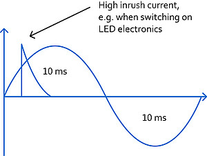
Figure 1
Selective RCCB (S) type A
A selective RCCB type A is marked with an S in the product description. This breaker is used in upstream electrical distribution boards (EDB) see figure 2. The reason to use them is that the RCCB immediately linked to the faulty circuit should trip. Attention: This has nothing to do with the protection of electric charging stations. A selective A type RCCB is not for human protection and never available in 30mA tripping current.
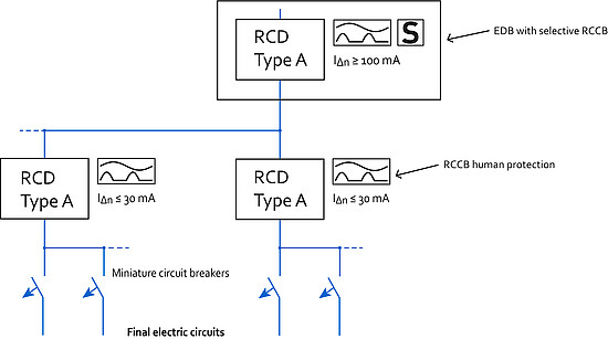
Figure 2
Brief summary: Neither a Type A RCCB (short-time delayed) nor a selective RCCB typ A is technically suitable for charging stations according to the standard.
EV Charging: Technical State of the art & regulations
Wherever sockets used in accordance to IEC 62196 the provision of protective measures for DC residual currents quote the appropriate measures shall be:
RCD Type B
or
Type A where the installation incorporates a method* of detecting DC residual currents,
>6 mA which results in disconnection of the AC supply from the charge point.
* In accordance to IEC 62955 there are two different ways to do it
1.) RDC-MD: Two seperate devices: type A 30mA RCCB + 6mA DC detection over transformer
2.) RDC-PD: Combined device: Type A 30mA RCCB and 6mA DC detection
EV Charging: How to do it right in practice
EV Charging Installations containing RCDs in series – Single charge point (TT-System)
Where installation design / regulations require RCDs to be connected in series,the upstream RCD will be subjected to the same residual currents as the charge point RCD. Consequently, the upstream RCD Type must be selected, based on the total dc residual current produced under fault conditions. In figure 3, the supply feeds a single charge point incorporating 6 mA dc residual current detection. The upstream RCD will only be subjected to a dc residual current < 6 mA. In this case, it is safe to install a Type A RCD as the the upstream device i.e. Type A can be used with < 6 mA dc and still provide the required level of protection. If a Type B RCD is installed in the Wallbox, then the upstream RCD must be Type B, because the tripping characteristics are different i.e. 15 <60 mA dc for 30 mA AC.
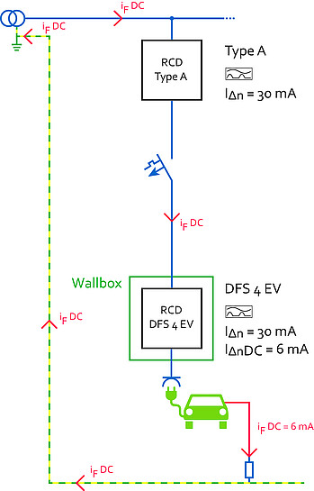
Figure 3
EV Charging Installations containing RCDs in series – Multiple charge points (TT-System)
In figure 3, the upstream RCD protecting the feeder cable, will be subjected to the combined leakage currents of the downstream charge points, and must be selected accordingly. In figure 4, the supply feeds two charge points incorporating 6 mA dc residual current detection. The upstream RCD protecting the feeder cable, will be subjected to the combined leakage currents of the downstream charge points, and must be selected accordingly i.e. Type B The other solution to consider which may be more cost effective: Install two separate feeders as per fig 2 i.e. the cost of two separate Type A devices rated for the down stream load + additional space and wiring, compared to the cost of one Type B RCD rated for the total load on the feeder. Where this is not possible, then Type B must be used for the main feeder RCD, to provide the level of protection required by the Regulations.
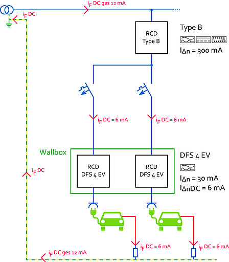
Figure 4
The levels of dc residual current, leakage currents and transient currents vary, based on the EV make and model. Local authorities and private companies offering public and or staff charging facilities, have no control over the EVs that will be connected to their EV infrastructure, and therefore, need to cater for the worst